The new firmware M79 for K11 R2R is now available!

K11 R2R firmware download link and update instruction: Click here
How to enable 1Bbit DSD native decoding:
On the homepage, hold the volume knob for about 2s to enter the Settings menu. Rotate the knob to switch the settings menu DSD DOP to DSD 1Bit. Then short press the knob to confirm the setting.
1. K11 R2R new firmware M79, now supports 1bit DSD native decoding!
Since its launch, the K11 R2R's 24bit R2R DAC sound quality has received widespread recognition and praise. We sincerely appreciate your support.
After release, we maintained close communication with users and received requests about implementing DSD native decoding on the K11 R2R. Through relentless efforts by our engineers, the K11 R2R now achieves 1bit DSD native decoding! Interested users can upgrade firmware to experience this (Note: the K11 R2R doesn't support OTA upgrades. Please download the upgrade tool on the PC for manual upgrade). We would like to receive your feedback on the listening experience after trying the new firmware. Thank you!

2. How can one circuit achieve both PCM R2R and 1bit R2R?
2.1 Basic principle
The R2R network in the K11 R2R adopts classic connection architecture, operating differently under various modes:
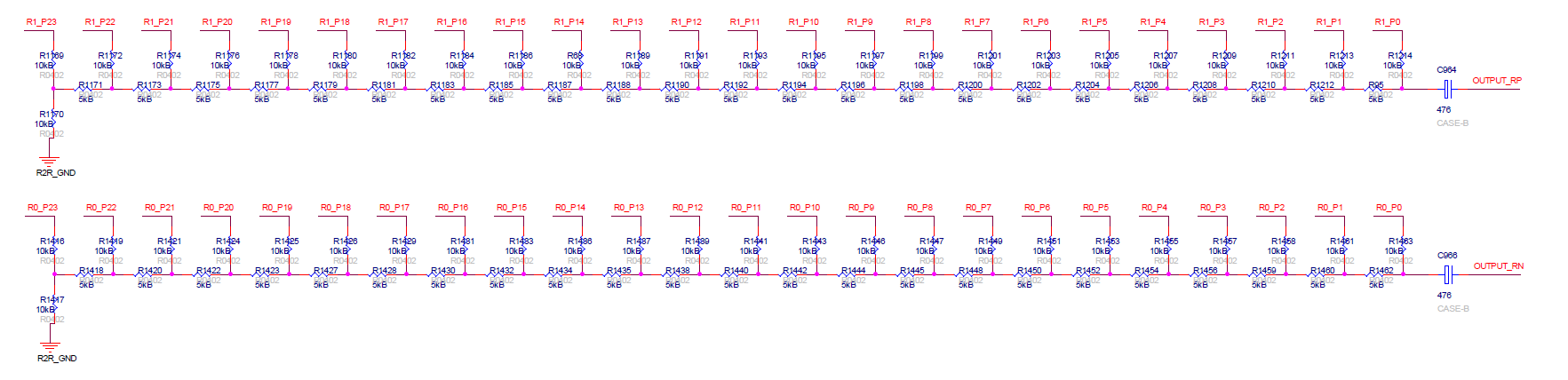
The same set of R2R hardware implements both PCM and 1bit DSD native decoding modes through different FPGA timing control:
If the input signal is PCM or DSD operating in D2P mode, the R2R network functions as a voltage divider. For example, with PCM192K, it outputs a voltage to the subsequent headphone amplifier circuit every 1/192K = 5.2μs.
If the input signal is DSD and operates in 1bit mode, the R2R network functions as an FIR filter. For example, with DSD64, it outputs a voltage to the subsequent headphone amplifier circuit every 1/2.8224M = 0.35us.
2.2 Working principle of 1bit DSD native decoding
When the input signal is DSD and the menu is set to 1bit mode, the R2R network functions as an FIR filter, sequentially processing the DSD signal, effectively acting as an FIR-DAC. The specific working principle is as follows: The weight of each bit is exactly half of the previous bit. For example, if b0 is 1, then b1 is 0.5, b2 is 0.25, b3 is 0.125, and so on. All input DSD signals are superimposed at the output and delivered as a voltage, forming a 24-tap FIR filter with coefficients precisely matching 1, 0.5, 0.25, 0.125...
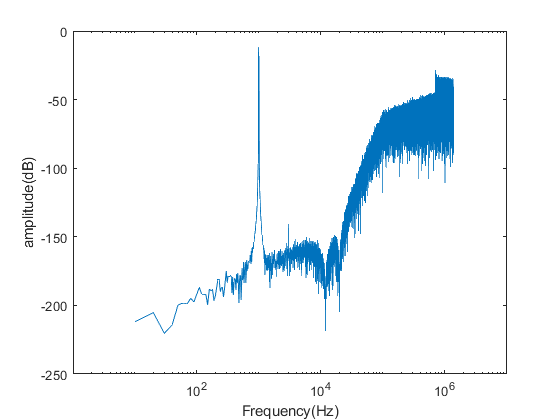
DSD signals are essentially analog signals modulated via Delta-Sigma Modulation (DSM) at a specific sampling rate. It inherently contains the original analog signal's information. For instance, a 1kHz sine wave in DSD64 exhibits a frequency response similar to the figure below: the left half represents the valid signal, while the right half consists of noise introduced by DSM modulation. The FIR-DAC fundamentally constructs an analog FIR filter. When the DSM-modulated signal passes through this FIR filter, the high-frequency noise is filtered out, leaving only the valid signal. However, since the R2R network is not specifically designed for DSM-based FIR-DAC, an additional active low-pass filter (LPF) is required for secondary filtering after the R2R stage. This two-stage process ultimately reproduces the original analog signal.
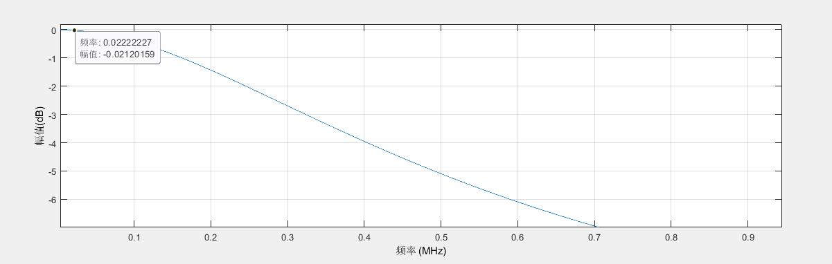
As shown in the frequency response diagram calculated from the coefficients, for DSD64, the in-band attenuation at 20kHz is less than 0.1dB, ensuring normal frequency response without affecting the audio band. Combined with the subsequent active LPF, the dual filtering removes the modulated noise from the DSD signal, recovering the original analog signal and enabling direct conversion of DSD to analog.